WAMS - Wings Angle Measuring System
MANUAL
~ +/- 0.1 degree accuracy ( instrument accuracy)
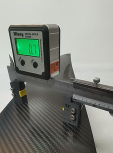
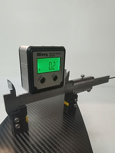
With our WAMS system you can measure and Calibrate easily your foil (wing angles) in 4 steps :
A. Measuring angles between Fuselage - front wing - rear wing : ( called : "angle of incidence" )
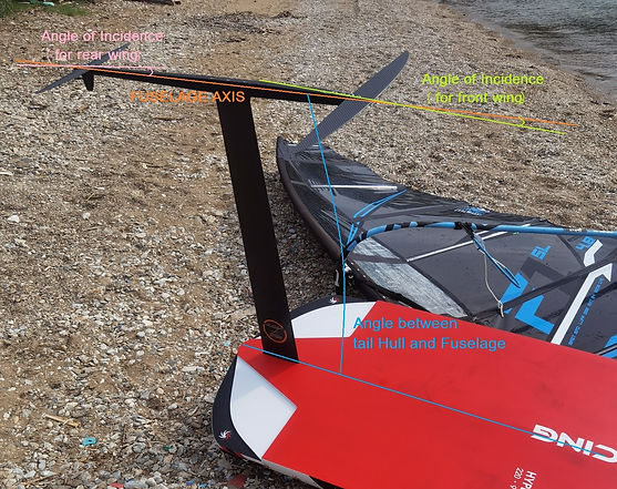
Definition : ( Angle of incidence AoI ) : the angle between the chord line of the wing where the wing is mounted to the fuselage, and a reference axis along the fuselage . We use it either for front wing and rear wing angles refered to the fuselage. The angle of incidence is fixed in the design of the windfoil, and cannot be varied in flight.
Angle of Incidence (AoI)
pics 1 : Angle of Incidence (AOI) - definition - ( aircraft , windfoil , wingfoil etc )
Definition : Angle of Attack (AoA) : it is something different.
Has to do with air (water flow) . Is the angle
of airflow (or water flow) relatively to the chord line
Note: If the airflow direction with the fuselage axis velocity direction are the same then, AoI = AoA (see pic above)
INSTRUCTIONS using the WAMS
1. Mount your foil - (no need to mount the mast at this stage - but it helps - ) and place it "upside down" )
2. Place the "Digital angle measuring system" on the fuselage and set it to 0° (reference angle = 0° )
(select an area that is parallel to the axis line of the fuselage .. (usually the mounting bolts on the mast area )
3.Place the Vernier Caliper with Digital angle measuring system on the front wing and read the angle (for example..+1.3°)
It is critical to place correctly these two parts.
Need to be placed correctly on the Leading Edge (LE) and
Trailing Edge (TE) as pictures show.
4.Place the Vernier Caliper with Digital angle measuring system on the rear wing and read the angle (for example ..-2.0°)
( !! the rear wing has to be mounted with a certain shim supplied from your foil brand (- if any -) !! )
Also the angles can be also positive if the geometry of the wing is assymetric etc etc.
=> Conclusion : Now we know that the relative angles between front wing - fuselage - rear wing are : +1.3° / 0 ° / -2°
(Angles of Incidence)
B. Measuring angles between : board tail hull - Fuselage - front wing - rear wing (5 steps ) :
1. mount your foil on the board and turn the board "upside down"
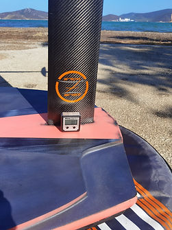
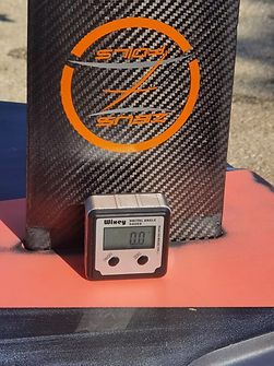
2. Place the "Digital angle measuring system" on the board tail hull (close to the mast area and set it to 0° (reference angle = 0° )
3. Place the "Digital angle measuring system" on the fuselage and read the angle (for example .. angle = 0° )
=> if you measure 0° that means that the fuselage is parallel with the board hull (same with reference angle )
(select an area that is parallel to the axis line of the fuselage .. (usually the mounting bolts on the mast area )
4.Place the Vernier Caliper with Digital angle measuring system on the front wing and read the angle (for example..+1.3°)
It is critical to place correctly these two parts.
Need to be placed correctly on the Leading Edge (LE) and
Trailing Edge (TE) as pictures show.
5.Place the Vernier Caliper with Digital angle measuring system on the rear wing and read the angle (for example ..-2°)
=> Conclusion : Now we know that the relative angles between :
tail board hull - front wing - fuselage - rear wing are : 0° / +1.3° / 0 ° (0.1°) / -2°
Important : Your brand dealer , designer or ..etc .. has to tell you the desired front wing angle relatively to the hull (tail area) so you can setup correctly your foil.
C. MINIMIZING DRAG vs ANGLE OF ATTACK
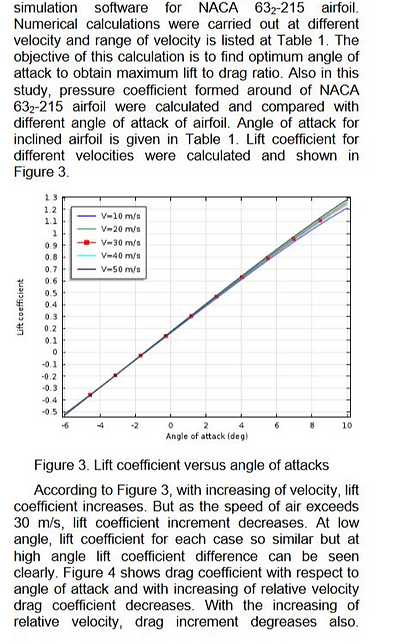
There's a certain "Angle of Attack - (AoA) " for every wing that for a big range of speed conditions this wing has the minimum drag. On the picture below the 're two diagrams showing something very interesting ( for wing : NACA63(2)215) :
According to figure3 ,the lift coefficient increases as AoA increases . Also increases with increasing of velocity. (up to ~10°)
According to figure 5 , the lift to drag ratio increases first as AoA increases and then decreases (after ~4° AoA) for all speed.
On foiling (mostly on racing foiling) we don't try to setup the wings to maximize the lift/drag ratio !!
We are trying to find the AoA of the certain wing we use in order to minimize the drag coefficient !!
So we can emphasize to the following (for example : for wing 63(2)215 ) :
For a wide range of velocities (from 10 to 50m/sec) we see from the figure 4 that minimum drag coefficient observes at around -1° to 0° AoA.
With that way we can extract very useful conclusions about our wings setups , positioning angles etc having a clear view of our whole foiling system.






 |  |
|---|---|
 |  |
 |  |
 |  |
 |  |
 |  |
 |  |
 |  |
 |  |
 |  |
 |  |
 |  |
 |  |
 |  |
 |  |
 |  |
 |
Head Shims for regulating wing angles/mast rake

Head Shims ... 3,4,5,6,7,8mm
(to be inserted for setting the appropriate wing angles and relative mast rake)

